
-
Products
Servo Balancing Hoists Read more
Server Lifter Read more
Vacuum Tube Lifters Read more
FULLSHARP Manipulators Read more
Pneumatic Jib Cranes Read more
Standard Structures Read more
FULLSHARP Rail Systems Read more
Lifts All Read more
Vacuum Lifting Pads Read more
Smart Electric Lifters (Taiwan) Read more
Smart Electric Lifters (China) Read more
Mini Cranes Read more
Air balancer Read more
Knight Global Servo Hoists Read more
Knight Global Manipulators Read more
Knight Global Rails Read more
Custom-designed lifters Read more
Electric Tow Tractors Read more
Plastic-Coated Steel Pipes Read more
Hoists Read more
Other Knight Global Products Read more
COMEUP Winches Read more
All products Servo Balancing Hoists Server Lifter Vacuum Tube Lifters FULLSHARP Manipulators Pneumatic Jib Cranes Standard Structures FULLSHARP Rail Systems Lifts All Lifts All Baggage Handling Lifts All by Industry Lifts All Cranes Lifts All Air Balancers Lifts All Custom Lifting Tools Lifts All Standard Grippers Vacuum Lifting Pads Metal sheet lifting Glass panel lifting for installation Glass panel lifting for production Custom vacuum lifters ANVER Smart Electric Lifters (Taiwan) Smart Electric Lifters (China) Mini Cranes Semi-automatic mini cranes 400-500-1000kg Automatic mini cranes 1000-2000kg Air balancer Knight Global Servo Hoists Knight Global Manipulators Knight Global Rails Custom-designed lifters Electric Tow Tractors Plastic-Coated Steel Pipes Hoists COMEUP Electric Hoists ENDO Air Hoists & Balancers KITO Hoists Other Knight Global Products COMEUP Winches COMEUP Gear Motor COMEUP AC Winch COMEUP Defense & Security Winch COMEUP Automotive Winch COMEUP Powersports Winch COMEUP Industrial Winch COMEUP Industrial Hoist COMEUP Earlier Products - What do you need to lift
- Contact
Overview
Knight eRail is a fully enclosed power supply rail for servo systems, VFD tractors and power tools running on ERAD aluminum rail. The conductor rail mounts on top of or beside the load rail.
Electrified Rail Systems are a complete power supply suspension system that can be used in combination with a Knight Servo System, VFD tractors, power tools, and other electrical devices.
The ERAD Series is a fully enclosed electrical system that eliminates the stack-up of runway festooning. The power travels through a conductor power rail (ERail), mounted on top of Knight’s ERAD4000, ERAD6000, or ERAD7000 ergonomically friendly aluminum rail. The standard ERail is equipped with (4) four poles, nominal current 60 amp, 240/480V which can run multiple systems on (1) one rail assembly.
The Electrified Rail is incredibly diverse in that it can also be mounted to the side of the aluminum rail. The benefits to this configuration include shorter stack-up heights and the use of Knight’s standard rail rather than the custom rail used with the top-mounted style. The side-mounted style can also be retrofitted onto an existing Knight system to eliminate the need for electrical festooning.
*Top-mounted style is Patent Pending
General Information
Features
- Patent Pending
- Fully Enclosed Electrical System
- ERail Electrical Capacity:
Up to 60 amps / 690 volts - Horizontal curved sections available.
- Max Weight Capacity:
Up to 3,000 lbs [1,360 kg] - Compliant with International Standards.
- Added safety against shock.
- Knight’s unique hanger design allows for adjustments while leveling the system.
Benefits
- Optional mounting configuration: side mounted.
- Eliminates stack-up of festooning trolleys and hanging electrical cables.
- Simplifies installation by including electrical rail within suspension.
- Eliminates need for tow bars.
- Stacked compact design eliminates need from installing load rail and power rail separately.
- Twice the power of the competition.
System Components
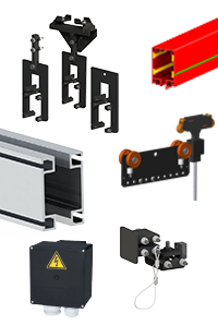 ERail
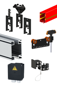
Available in 4 poles with a nominal current of 60 A.
ERail Conductor Trolley
Travels inside of the ERail and is combined with the Knight load trolley. Copper graphite shoes are used for energy and control voltages over 35 V.
ERAD4000/ERAD6000/ERAD7000
Combined with Knight’s load trolleys, provides the most ergonomically friendly rail system. Rail comes in lengths up to 25ft [9.1m] without a splice. Capacities up to 3,000 lbs. [1,360 kg].
Suspension Points
Knight adjustable hangers and End Trucks support both the Load Rail and ERail. Hangers have the ability to mount to I-Beams, C-Channels, Angle Iron, and many others.
ERail End Caps and Stops
Attaches to the end of the ERail Series Rail. The Redundant End Cap is primarily used to prevent load and ERail trolleys from exiting the rail.
Power Supply End Feed
Power supply feed for ERail. Comes standard with 4 poles.
ERAD4000 Capacity Chart
ERAD4000 Capacities
| Hanger Span | Deflection Criteria | ||||||
|---|---|---|---|---|---|---|---|
| 1:350 Capacity* | 1:450 Capacity* | 1:550 Capacity* | |||||
| ft | m | lbs | kg | lbs | kg | lbs | kg |
| 5 | 1.52 | 1140 | 517 | 1140 | 517 | 1140 | 517 |
| 6 | 1.83 | 945 | 429 | 945 | 429 | 945 | 429 |
| 7 | 2.13 | 810 | 367 | 810 | 367 | 790 | 358 |
| 8 | 2.45 | 705 | 320 | 705 | 320 | 600 | 272 |
| 9 | 2.74 | 625 | 283 | 575 | 261 | 470 | 213 |
| 10 | 3.05 | 560 | 254 | 460 | 209 | 375 | 170 |
| 11 | 3.35 | 490 | 222 | 375 | 170 | 300 | 136 |
| 12 | 3.66 | 405 | 184 | 310 | 141 | 245 | 111 |
| 13 | 3.96 | 340 | 154 | 255 | 116 | 205 | 93 |
| 14 | 4.27 | 285 | 129 | 215 | 98 | 170 | 77 |
| 15 | 4.57 | 240 | 109 | 180 | 82 | 140 | 64 |
| 16 | 4.88 | 205 | 93 | 150 | 68 | 120 | 54 |
| 17 | 5.18 | 175 | 79 | 130 | 59 | 100 | 45 |
| 18 | 5.49 | 150 | 68 | 110 | 50 | 80 | 36 |
| 19 | 5.79 | 130 | 59 | 90 | 41 | 65 | 29 |
| 20 | 6.10 | 110 | 50 | 75 | 34 | 55 | 25 |
| 21 | 6.40 | 90 | 41 | 60 | 27 | 40 | 18 |
| 22 | 6.71 | 80 | 36 | 50 | 23 | 30 | 14 |
| 23 | 7.01 | 65 | 29 | 40 | 18 | 20 | 9 |
| 24 | 7.32 | 50 | 23 | 30 | 14 | 15 | 7 |
*Due to Ergonomic considerations, each rail span distance is tested to determine the maximum single point load required to achieve a predetermined deflection based on a ratio of 1:350 (1” of deflection for each 350” of length), 1:450 (1” of deflection in 450” of length) or 1:550 (1” of deflection for each 550” of length).
For purposes of estimating approximate ergonomic force requirements, the following formula may be used:
0.009 x total mass = maximum effort (in lbf) required to overcome inertia. Effort required to sustain movement is generally 0.35 x effort to overcome inertia e.g.,
250 lbs. (1.03 kg) mass x 0.009 = 2.25 lbf (0.9 kg) to overcome inertia
2.25 (0.9 kg) x 0.35 = .79 lbf (0.36 kg) to sustain movement
ERAD6000 Capacity Chart
ERAD6000 Capacities
| Hanger Span | Deflection Criteria | ||||||
|---|---|---|---|---|---|---|---|
| 1:350 Capacity* | 1:450 Capacity* | 1:550 Capacity* | |||||
| ft | m | lbs | kg | lbs | kg | lbs | kg |
| 5 | 1.52 | 2030 | 921 | 2030 | 921 | 2030 | 921 |
| 6 | 1.83 | 1690 | 767 | 1690 | 767 | 1690 | 767 |
| 7 | 2.13 | 1445 | 655 | 1445 | 655 | 1445 | 655 |
| 8 | 2.45 | 1260 | 572 | 1260 | 572 | 1260 | 572 |
| 9 | 2.74 | 1115 | 506 | 1115 | 506 | 1115 | 506 |
| 10 | 3.05 | 1000 | 454 | 1000 | 454 | 895 | 406 |
| 11 | 3.35 | 905 | 411 | 900 | 408 | 730 | 331 |
| 12 | 3.66 | 825 | 374 | 750 | 340 | 605 | 274 |
| 13 | 3.96 | 760 | 345 | 630 | 286 | 510 | 231 |
| 14 | 4.27 | 700 | 318 | 535 | 243 | 430 | 195 |
| 15 | 4.57 | 600 | 272 | 455 | 206 | 365 | 166 |
| 16 | 4.88 | 520 | 236 | 395 | 134 | 310 | 141 |
| 17 | 5.18 | 450 | 204 | 340 | 154 | 270 | 122 |
| 18 | 5.49 | 395 | 179 | 295 | 134 | 230 | 104 |
| 19 | 5.79 | 345 | 156 | 255 | 116 | 195 | 88 |
| 20 | 6.10 | 300 | 136 | 220 | 100 | 170 | 77 |
| 21 | 6.40 | 265 | 120 | 190 | 86 | 145 | 66 |
| 22 | 6.71 | 230 | 104 | 165 | 75 | 125 | 57 |
| 23 | 7.01 | 205 | 93 | 140 | 64 | 105 | 48 |
| 24 | 7.32 | 180 | 82 | 120 | 54 | 85 | 39 |
*Due to Ergonomic considerations, each rail span distance is tested to determine the maximum single point load required to achieve a predetermined deflection based on a ratio of 1:350 (1” of deflection for each 350” of length), 1:450 (1” of deflection in 450” of length) or 1:550 (1” of deflection for each 550” of length).
For purposes of estimating approximate ergonomic force requirements, the following formula may be used:
0.009 x total mass = maximum effort (in lbf) required to overcome inertia. Effort required to sustain movement is generally 0.35 x effort to overcome inertia e.g.,
250 lbs. (1.03 kg) mass x 0.009 = 2.25 lbf (0.9 kg) to overcome inertia
2.25 (0.9 kg) x 0.35 = .79 lbf (0.36 kg) to sustain movement
ERAD7000 Capacity Chart
ERAD7000 Capacities
| Hanger Span | Deflection Criteria | ||||||
|---|---|---|---|---|---|---|---|
| 1:350 Capacity* | 1:450 Capacity* | 1:550 Capacity* | |||||
| ft | m | lbs | kg | lbs | kg | lbs | kg |
| 5 | 1.52 | 3000 | 1360 | 3000 | 1360 | 3000 | 1360 |
| 6 | 1.83 | 3000 | 1360 | 3000 | 1360 | 3000 | 1360 |
| 7 | 2.13 | 3000 | 1360 | 3000 | 1360 | 3000 | 1360 |
| 8 | 2.45 | 2940 | 1334 | 2940 | 1334 | 2940 | 1334 |
| 9 | 2.74 | 2610 | 1184 | 2610 | 1184 | 2610 | 1184 |
| 10 | 3.05 | 2345 | 1064 | 2345 | 1064 | 2345 | 1064 |
| 11 | 3.35 | 2130 | 966 | 2130 | 966 | 2130 | 966 |
| 12 | 3.66 | 1945 | 882 | 1945 | 882 | 1945 | 882 |
| 13 | 3.96 | 1795 | 814 | 1795 | 814 | 1720 | 780 |
| 14 | 4.27 | 1660 | 753 | 1660 | 753 | 1475 | 669 |
| 15 | 4.57 | 1545 | 701 | 1545 | 701 | 1275 | 578 |
| 16 | 4.88 | 1445 | 655 | 1370 | 621 | 1110 | 503 |
| 17 | 5.18 | 1355 | 615 | 1205 | 547 | 975 | 442 |
| 18 | 5.49 | 1280 | 581 | 1065 | 483 | 860 | 390 |
| 19 | 5.79 | 1205 | 547 | 950 | 431 | 765 | 347 |
| 20 | 6.10 | 1105 | 501 | 845 | 383 | 680 | 308 |
| 21 | 6.40 | 995 | 451 | 760 | 345 | 610 | 277 |
| 22 | 6.71 | 895 | 406 | 685 | 311 | 545 | 247 |
| 23 | 7.01 | 810 | 367 | 615 | 279 | 490 | 222 |
| 24 | 7.32 | 735 | 333 | 555 | 252 | 440 | 200 |
*Due to Ergonomic considerations, each rail span distance is tested to determine the maximum single point load required to achieve a predetermined deflection based on a ratio of 1:350 (1” of deflection for each 350” of length), 1:450 (1” of deflection in 450” of length) or 1:550 (1” of deflection for each 550” of length).
For purposes of estimating approximate ergonomic force requirements, the following formula may be used:
0.009 x total mass = maximum effort (in lbf) required to overcome inertia. Effort required to sustain movement is generally 0.35 x effort to overcome inertia e.g.,
250 lbs. (1.03 kg) mass x 0.009 = 2.25 lbf (0.9 kg) to overcome inertia
2.25 (0.9 kg) x 0.35 = .79 lbf (0.36 kg) to sustain movement
Videos
*ERail Electrified Rail Systems
Accessories
General 3
- Weight
- 0.14 lbs. [0.06kg]
Details
The EMRMA6172 Cord Clamp is used in conjunction with the ERail trolley to prevent damage to the electrical cable as the trolley travels through the rail.- Secures electrical cord for the power.
- Used in conjunction with the ERail trolley to prevent damage to the cable.
- Weight
- 1.5 lbs. [0.68kg]
- Lengths
- 1 meter cable, 3 meter cable
Details
The EMRTA6196 Conductor Trolley travels inside of the red ERail and carries power to the electrical tools/fixtures on the rail system. It is combined with the Knight Load Trolley. Copper graphite shoes are used for energy and control voltages over 35 V. The ERail Conductor Trolley comes with a protective cord clamp (EMRMA6172) to help prevent damage to the electrical cable. Cable available in 1 or 3 meter lengths. Available in 240VAC, single phase (15 or 20AMP) or 480VAC, three phase (20 or 30AMP) power. When ordering, must specify with this format: EMRTA6196-(240 or 480VAC)-(15, 20, or 30AMP)-(1 or 3 meter cable). Part Numbers: EMRTA6196-240-15-1, EMRTA6196-240-15-3, EMRTA6196-240-20-1, EMRTA6196-240-20-3 EMRTA6196-480-20-1, EMRTA6196-480-20-3, EMRTA6196-480-30-1, EMRTA6196-480-30-3- Travels inside of the ERail.
- Carries power to the electrical tools on the ERail System.
- Copper graphite shoes are used for energy and control voltages over 35 V.
- 240VAC, single phase or 480VAC, 3 phase power.
- Includes the EMRMA6172 Cord Clamp.
- 15AMP, 20AMP, or 30AMP
- Includes 1 meter or 3 meter electrical cable.
- Weight
- 20 lbs. [9kg]
Details
The KSAA1080 ERail Maintenance Cleaning Trolley is used to maintain and clean the inside of the electrified rail. Over time, verdigris will develop on the inside of the electrified rail and the nylon brushes of the KSAA1080 will gently scrub that away without causing damage to the ERail. The Maintenance Cleaning Trolley consists of a modified rail trolley with a slot to insert the nylon brush assembly.- Used to clean the inside of the electrified rail.
- Equipped with a nylon brush trolley for cleaning.
Hangers 14
- Weight
- 8.7 lbs. [3.9kg].
Details
Knight's EMRHA4161 C-Channel Hanger Assembly is used for Direct or Offset Loads and suspends Knight’s ERAD4000 Series Aluminum Rail Systems and ERail. It can attach to all C-Channel or Angle Iron. When using the EMRHA4161 Hanger, structural steel can be run perpendicular or parallel to the Knight rail system.- Suspends Knight’s ERAD4000 series rail and Knight’s ERail.
- For Direct or Offset loads.
- Attaches to all C-Channel or Angle Iron.
- Adjustable Hanger Height.
- Structural steel can be run perpendicular or parallel to the rail system.
- Weight
- 6.6 lbs. [3kg].
Details
The EMRHA4165 C-Channel Hanger Sub-Assembly is used for Direct or Offset Loads and suspends Knight’s ERAD4000 Series Aluminum Rail Systems and the ERail. When using the EMRHA4165 Hanger, structural steel can be run perpendicular or parallel to the Knight rail system.- Suspends Knight’s ERAD4000 series rail and Knight’s ERail.
- For Direct or Offset loads.
- Steel can be run parallel or perpendicular to the rail system.
- Weight
- 5.2 lbs [2.36kg]
Details
Used for Direct or Offset Loads and suspends Knight’s ERAD4000, ERAD6000 or ERAD7000 Rail Systems. When using the EMRHA6160 Hanger, structural steel can be run perpendicular or parallel to the Knight rail system.- Suspends Knight’s ERAD4000, ERAD6000, or ERAD7000 Series Rail.
- For Direct or Offset Loads.
- Fixed Height Hanger.
- Hanger is clamped to the top flange of the Knight rail.
- Coated with an environmentally friendly corrosion protection. ** (Autophoretic ACC 900®).
- Attaches to all C-Channel or Angle Iron.
- Weight
- 9.7 lbs. [4.41kg]
Details
The EMRHA6161 C-Channel Hanger Sub-Assembly is used for Direct or Offset Loads and suspends Knight’s ERAD6000 Series Aluminum Rail Systems and the ERail. When using the EMRHA6161 Hanger, structural steel can be run perpendicular or parallel to the Knight rail system.- Suspends Knight’s ERAD6000 series rail and Knight’s ERail.
- For Direct or Offset loads
- Steel can be run parallel or perpendicular to the rail system.
- Adjustable Hanger Height.
- Weight
- 9.7 lbs. [4.4kg].
Details
The EMRHA6165 C-Channel Hanger Sub-Assembly is used for Direct or Offset Loads and suspends Knight’s ERAD6000 Series Rail and ERail. When using the EMRHA6165 Hanger, structural steel can be run perpendicular or parallel to the Knight rail system.- Suspends Knight’s ERAD6000 series rail and Knight’s ERail.
- For Direct or Offset loads
- Steel can be run parallel or perpendicular to the rail system.
- Adjustable Hanger Height.
- Weight
- 9.7 lbs. [4.41kg]
Details
The EMRHA7161 C-Channel Sub-Assembly Hanger is used for Direct or Offset Loads and suspends Knight’s ERAD7000 Series Aluminum Rail Systems and the ERail. When using the EMRHA7161 Hanger, structural steel can be run perpendicular or parallel to the Knight rail system.- Suspends Knight’s ERAD7000 series rail and Knight’s ERail.
- For Direct or Offset loads
- Steel can be run parallel or perpendicular to the rail system.
- Adjustable Hanger Height.
- Weight
- 9.7 lbs. [4.41kg]
Details
The EMRHA7165 ERail C-Channel Sub-Assembly Hanger is used for Direct or Offset Loads and suspends Knight’s ERAD7000 Series Aluminum Rail Systems and the ERail. When using the EMRHA7165 Hanger, structural steel can be run perpendicular or parallel to the Knight rail system.- Suspends Knight’s ERAD7000 series rail and Knight’s ERail.
- For Direct or Offset loads
- Steel can be run parallel or perpendicular to the rail system.
- Adjustable Hanger Height.
- Weight
- 17.5 lbs. [7.95kg].
Details
The EMRHS4162 Extending Stack I-Beam Hanger is used for Direct or Offset Loads and suspends Knight’s ERAD4000 Series Aluminum Rail Systems and ERail. When using the EMRHS4162 Hanger, structural steel can be run perpendicular or parallel to the Knight rail system.- Suspends Knight’s ERAD4000 series rail and Knight’s ERail.
- For Direct or Offset loads
- Steel can be run parallel or perpendicular to the rail system.
- Structural Support Flange Size: 2 in. – 7 in. [51mm – 178mm].
- Adjustable Hanger Height.
- Weight
- 19 lbs [8.64kg]
Details
The EMRHS4262 Extending Stack I-Beam Hanger is used for Direct or Offset Loads and suspends Knight’s ERAD4000 Series Aluminum Rail Systems and ERail. When using the EMRHS4262 Hanger, structural steel can be run perpendicular or parallel to the Knight rail system.- Suspends Knight’s ERAD4000 series rail and Knight’s ERail.
- For Direct or Offset loads
- Steel can be run parallel or perpendicular to the rail system.
- Structural Support Flange Size: 7 in. – 11 in. [178mm – 279mm].
- Adjustable Hanger Height.
- Weight
- 18.3 lbs [8.29kg]
Details
The EMRHS6162 Extending Stack I-Beam Hanger is used for Direct or Offset Loads and suspends Knight’s ERAD6000 Series Aluminum Rail Systems and ERail. When using the EMRHS6162 Hanger, structural steel can be run perpendicular or parallel to the Knight rail system.- Suspends Knight’s ERAD6000 series rail and Knight’s ERail.
- For Direct or Offset loads
- Steel can be run parallel or perpendicular to the rail system.
- Structural Support Flange Size: 2 in. – 7 in. [51mm – 178mm].
- Adjustable Hanger Height.
- Weight
- 13.8 lbs [6.26kg]
Details
Used for Direct Loads and suspends Knight’s ERAD4000, ERAD6000 or ERAD7000 Series Rail Systems. This hanger is for the non-electrified side of an ERail System. When using the EMRHS6163 Hanger, structural steel can be run perpendicular or parallel to the Knight rail system. Coated with an environmentally friendly corrosion protectant.- For Direct Loads.
- Structural Support Flange Size: 2 in.- 7 in. [51mm – 178mm].
- Used for the non-electrified side of an ERail system.
- Coated with an environmentally friendly corrosion protection. ** (Autophoretic ACC 900®).
- Adjustable Height Hanger.
- Weight
- 19.8 lbs [8.98kg]
Details
The EMRHS6262 Extending Stack I-Beam Hanger is used for Direct or Offset Loads and suspends Knight’s ERAD6000 Series Aluminum Rail Systems and ERail. When using the EMRHS6262 Hanger, structural steel can be run perpendicular or parallel to the Knight rail system.- Suspends Knight’s ERAD6000 series rail and Knight’s ERail.
- For Direct or Offset loads
- Steel can be run parallel or perpendicular to the rail system.
- Structural Support Flange Size: 7 in. – 11 in. [178mm – 279mm].
- Adjustable Hanger Height.
- Weight
- 24.7 lbs. [11.2kg].
Details
The EMRHS7162 Extending Stack I-Beam Hanger is used for Direct or Offset Loads and suspends Knight’s ERAD7000 Series Aluminum Rail Systems and ERail. When using the EMRHS7162 Hanger, structural steel can be run perpendicular or parallel to the Knight rail system.- Suspends Knight’s ERAD7000 series rail and Knight’s ERail.
- For Direct or Offset loads.
- Steel can be run parallel or perpendicular to the rail system.
- Structural Support Flange Size: 2 in. – 7 in. [51mm – 178mm].
- Adjustable Hanger Height.
- Weight
- 20.1 lbs [9.11kg]
Details
The EMRHS7262 Extending Stack I-Beam Hanger is used for Direct or Offset Loads and suspends Knight’s ERAD7000 Series Aluminum Rail Systems and ERail. When using the EMRHS7262 Hanger, structural steel can be run perpendicular or parallel to the Knight rail system.- Suspends Knight’s ERAD7000 series rail and Knight’s ERail.
- For Direct or Offset loads
- Steel can be run parallel or perpendicular to the rail system.
- Structural Support Flange Size: 7 in. – 11 in. [178mm – 279mm].
- Adjustable Hanger Height.
Load Trolleys 17
- Weight
- 1.5 lbs. [0.68kg]
- Lengths
- 1 meter cable, 3 meter cable
Details
The EMRTA6196 Conductor Trolley travels inside of the red ERail and carries power to the electrical tools/fixtures on the rail system. It is combined with the Knight Load Trolley. Copper graphite shoes are used for energy and control voltages over 35 V. The ERail Conductor Trolley comes with a protective cord clamp (EMRMA6172) to help prevent damage to the electrical cable. Cable available in 1 or 3 meter lengths. Available in 240VAC, single phase (15 or 20AMP) or 480VAC, three phase (20 or 30AMP) power. When ordering, must specify with this format: EMRTA6196-(240 or 480VAC)-(15, 20, or 30AMP)-(1 or 3 meter cable). Part Numbers: EMRTA6196-240-15-1, EMRTA6196-240-15-3, EMRTA6196-240-20-1, EMRTA6196-240-20-3 EMRTA6196-480-20-1, EMRTA6196-480-20-3, EMRTA6196-480-30-1, EMRTA6196-480-30-3- Travels inside of the ERail.
- Carries power to the electrical tools on the ERail System.
- Copper graphite shoes are used for energy and control voltages over 35 V.
- 240VAC, single phase or 480VAC, 3 phase power.
- Includes the EMRMA6172 Cord Clamp.
- 15AMP, 20AMP, or 30AMP
- Includes 1 meter or 3 meter electrical cable.
- Max capacity
- 1, 140 [517kg]
- Weight
- 5.7 lbs [2.56kg]
Details
The EMRTA4176 Servo Trolley attaches to a Knight Servo Hoist and runs inside of the ERAD4000 Series Rail.- Attaches to a Knight Servo Hoist and runs inside of the ERAD4000 Series rail system.
- Fiberglass filled High Impact Nylon Wheels.
- Side Guide Rollers with integrated bearings.
- Double-shielded bearings keep dirt out and do not require lubrication.
- Max capacity
- 1, 140 [517kg]
- Weight
- 5.5 lbs [2.48kg]
Details
Knight Global’s EMRTA4190 Load Trolley transfers loads along the horizontal axis and suspends a load from The ERAD4000 Series Rail Systems. It attaches to the ERail’s conductor trolley.- Suspends a load from Knight’s ERAD4000 Series rail system.
- Fiberglass filled High Impact Nylon Wheels.
- Side Guide Rollers with integrated bearings.
- Double-shielded bearings keep dirt out and do not require lubrication.
- Max capacity
- 1, 140 [517kg]
- Weight
- 5.5 lbs [2.48kg]
Details
The EMRTA4192 Load Trolley with Yoke travels along a horizontal axis and suspends loads from the ERAD4000 Series rail system. The trolley’s yoke design allows for pivoting in the “X” and “Y” directions which creates freedom of movement. It attaches to the ERail’s conductor trolley.- Suspends a load from Knight’s ERAD4000 Series rail system.
- Fiberglass filled High Impact Nylon Wheels.
- Side Guide Rollers with integrated bearings.
- Double-shielded bearings keep dirt out and do not require lubrication
- Max capacity
- 1, 140 [517kg]
- Weight
- 4.9 lbs [2.22kg]
Details
Knight’s EMRTA4194 Low Profile Load Trolley suspends a load from the ERAD4000 Series Rail System. It attaches to the ERail’s conductor trolley.- Suspends a load from Knight’s ERAD4000 Series rail system.
- Fiberglass filled High Impact Nylon Wheels.
- Side Guide Rollers with integrated bearings.
- Double-shielded bearings keep dirt out and do not require lubrication.
- Max capacity
- 1, 140 [517kg]
- Weight
- 4.9 lbs [2.22kg]
Details
Knight’s EMRTA4195 Low Profile Load Trolley with Yoke suspends a load from the ERAD4000 Series Rail System. The trolley’s yoke design allows for pivoting in the “X” and “Y” directions which creates freedom of movement. It attaches to the ERail’s conductor trolley.- Suspends a load from Knight’s ERAD4000 Series rail system.
- Fiberglass filled High Impact Nylon Wheels.
- Side Guide Rollers with integrated bearings.
- Double-shielded bearings keep dirt out and do not require lubrication.
- Max capacity
- 2, 030 lbs. [920kg].
- Weight
- 11.2 lbs. [5.06kg].
Details
The EMRTA6176 Servo Trolley attaches to a Knight Servo Hoist and runs inside of the ERAD6000 Series Rail.- Attaches to a Knight Servo Hoist and runs inside of the ERAD6000 Series rail system.
- Fiberglass filled High Impact Nylon Wheels.
- Side Guide Rollers with integrated bearings.
- Double-shielded bearings keep dirt out and do not require lubrication.
- Max capacity
- 2, 030 lbs. [920kg].
- Weight
- 6.1 lbs. [2.77kg]
Details
Knight Global’s EMRTA6190 Load Trolley transfers loads along the horizontal axis and suspends a load from The ERAD6000 Series Rail Systems. It attaches to the ERail's conductor trolley.- Suspends a load from Knight’s ERAD6000 Series rail system.
- Fiberglass filled High Impact Nylon Wheels.
- Side Guide Rollers with integrated bearings.
- Double-shielded bearings keep dirt out and do not require lubrication.
- Max capacity
- 2, 030 lbs. [920kg].
- Weight
- 6.1 lbs. [2.77kg]
Details
The EMRTA6192 Load Trolley with Yoke travels along a horizontal axis and suspends loads from the ERAD6000 Series rail system. The trolley's yoke design allows for pivoting in the "X" and "Y" directions which creates freedom of movement. It attaches to the ERail's conductor trolley.- Suspends a load from Knight’s ERAD6000 Series rail system.
- Fiberglass filled High Impact Nylon Wheels.
- Side Guide Rollers with integrated bearings.
- Double-shielded bearings keep dirt out and do not require lubrication.
- Max capacity
- 2, 030 lbs. [920kg].
- Weight
- 7.7 lbs. [3.48kg].
Details
Knight's EMRTA6194 Low Profile Load Trolley suspends a load from the ERAD6000 Series Rail System. It attaches to the ERail's conductor trolley.- Suspends a load from Knight’s ERAD6000 Series rail system.
- Fiberglass filled High Impact Nylon Wheels.
- Side Guide Rollers with integrated bearings.
- Double-shielded bearings keep dirt out and do not require lubrication.
- Max capacity
- 2, 030 lbs. [920kg].
- Weight
- 7.7 lbs. [3.48kg].
Details
Knight's EMRTA6195 Low Profile Load Trolley with Yoke suspends a load from the ERAD6000 Series Rail System. The trolley's yoke design allows for pivoting in the "X" and "Y" directions which creates freedom of movement. It attaches to the ERail's conductor trolley.- Suspends a load from Knight’s ERAD6000 Series rail system.
- Fiberglass filled High Impact Nylon Wheels.
- Side Guide Rollers with integrated bearings.
- Double-shielded bearings keep dirt out and do not require lubrication.
- Max capacity
- 3, 000 lbs. [1, 360kg].
- Weight
- 16.8 lbs. [7.62 kg]
Details
The EMRTA7176 Servo Trolley attaches to a Knight Servo Hoist and runs inside of the ERAD7000 Series Rail.- Attaches to a Knight Servo Hoist and runs inside of the ERAD7000 Series rail system.
- Fiberglass filled High Impact Nylon Wheels.
- Side Guide Rollers with integrated bearings.
- Double-shielded bearings keep dirt out and do not require lubrication.
- Max capacity
- 3, 000 lbs. [1, 360kg].
- Weight
- 11.9 lbs. [5.38kg].
Details
Knight Global’s EMRTA7190 Load Trolley transfers loads along the horizontal axis and suspends a load from The ERAD7000 Series Rail Systems. It attaches to the ERail's conductor trolley.- Suspends a load from Knight’s ERAD7000 Series rail system.
- Fiberglass filled High Impact Nylon Wheels.
- Side Guide Rollers with integrated bearings.
- Double-shielded bearings keep dirt out and do not require lubrication.
- Max capacity
- 3, 000 lbs. [1, 360kg].
- Weight
- 14.5 lbs. [6.58kg].
Details
The EMRTA7192 Load Trolley with Yoke travels along a horizontal axis and suspends loads from the ERAD7000 Series rail system. The trolley's yoke design allows for pivoting in the "X" and "Y" directions which creates freedom of movement. It attaches to the ERail's conductor trolley.- Suspends a load from Knight’s ERAD7000 Series rail system.
- Fiberglass filled High Impact Nylon Wheels.
- Side Guide Rollers with integrated bearings.
- Double-shielded bearings keep dirt out and do not require lubrication.
- Max capacity
- 3, 000 lbs. [1, 360kg].
- Weight
- 11.5 lbs. [5.22kg]
Details
Knight's EMRTA7194 Low Profile Load Trolley with Yoke suspends a load from the ERAD7000 Series Rail System. It attaches to the ERail's conductor trolley.- Suspends a load from Knight’s ERAD7000 Series rail system.
- Fiberglass filled High Impact Nylon Wheels.
- Side Guide Rollers with integrated bearings.
- Double-shielded bearings keep dirt out and do not require lubrication.
- Max capacity
- 3, 000 lbs. [1, 360kg].
- Weight
- 11.5 lbs. [5.22kg]
Details
Knight's EMRTA7195 Low Profile Load Trolley with Yoke suspends a load from the ERAD7000 Series Rail System. The trolley's yoke design allows for pivoting in the "X" and "Y" directions which creates freedom of movement. It attaches to the ERail's conductor trolley.- Suspends a load from Knight’s ERAD7000 Series rail system.
- Fiberglass filled High Impact Nylon Wheels.
- Side Guide Rollers with integrated bearings.
- Double-shielded bearings keep dirt out and do not require lubrication.
- Weight
- 20 lbs. [9kg]
Details
The KSAA1080 ERail Maintenance Cleaning Trolley is used to maintain and clean the inside of the electrified rail. Over time, verdigris will develop on the inside of the electrified rail and the nylon brushes of the KSAA1080 will gently scrub that away without causing damage to the ERail. The Maintenance Cleaning Trolley consists of a modified rail trolley with a slot to insert the nylon brush assembly.- Used to clean the inside of the electrified rail.
- Equipped with a nylon brush trolley for cleaning.
End Trucks 6
- Max capacity
- 1, 140 [517kg]
- Weight
- 37.7 lbs. [17.11kg].
Details
Knight’s Rotating End Truck for ERAD4000 suspends Knight’s ERail and ERAD4000 Rail. The End Truck’s Yoke design allows for the pivoting in the “X” and “Y” directions which creates freedom of movement. The EMRES4181-4000 runs inside of Knight’s RAD4110 Series Rail.- Suspends Knight’s ERAD4000 Series Rail and ERail.
- The EMRES4181-4000 runs inside of the RAD4110 Series Rail.
- Yoke design allows for pivoting in the “X” and “Y” directions.
- Max capacity
- 1, 140 [517kg]
- Weight
- 37.7 lbs. [17.11kg].
Details
The EMRES4185 Low Profile Rotating End Truck suspends Knight’s ERAD4000 Series Rail and the ERail. The end truck’s yoke design allows for the pivoting in the “X” and “Y” directions which creates freedom of movement. The EMRES4185-4000 runs inside of Knight’s RAD4110 Series Rail.- Suspends Knight’s ERAD4000 Series Rail and the ERail.
- EMRES4185-4000 runs inside of Knight’s RAD4110 Series Rail.
- Yoke design allows for pivoting in the “X” and “Y” directions.
- Max capacity
- 2, 030 lbs. [920kg].
- Weight
- 37.7 lbs. [17.11kg]
Details
Knight's Rotating End Truck for ERAD6000 suspends Knight's ERail and ERAD6000 Rail. The End Truck's Yoke design allows for the pivoting in the "X" and "Y" directions which creates freedom of movement. EMRES6181-4000 runs inside of the RAD4110 Series Rail. EMRES6181-6000 runs inside of the RAD6110 Series Rail. EMRES6181-7000 runs inside of the RAD7510 Series Rail.- Suspends Knight’s ERAD6000 Series Rail and ERail.
- Yoke design allows for pivoting in the “X” and “Y” directions.
- The EMRES6181-4000 runs inside of the RAD4110 Series Rail.
- The EMRES6181-6000 runs inside of the RAD6110 Series Rail.
- The EMRES6181-7000 runs inside of the RAD7510 Series Rail.
- Max capacity
- 2, 030 lbs. [920kg].
- Weight
- 37.7 lbs. [17.11kg]
Details
The EMRES6185 Low Profile Rotating End Truck suspends Knight's ERAD6000 Series Rail and the ERail. The end truck's yoke design allows for the pivoting in the “X” and “Y” directions which creates freedom of movement. EMRES6185-4000 runs inside of the RAD4110 Series Rail. EMRES6185-6000 runs inside of the RAD6110 Series Rail. EMRES6185-7000 runs inside of the RAD7510 Series Rail.- Suspends Knight’s ERAD6000 Series Rail and the ERail.
- Yoke design allows for pivoting in the “X” and “Y” directions.
- EMRES6185-4000 runs inside of Knight’s RAD4110 Series Rail.
- EMRES6185-6000 runs inside of Knight’s RAD6110 Series Rail.
- EMRES6185-7000 runs inside of Knight’s RAD7510 Series Rail.
- Max capacity
- 3, 000 lbs. [1, 360kg].
- Weight
- 38.7 lbs. [17.56 kg].
Details
Knight's Rotating End Truck for ERAD7000 suspends Knight's ERail and ERAD7000 Rail. The End Truck's Yoke design allows for the pivoting in the "X" and "Y" directions which creates freedom of movement. EMRES7181-4000 runs inside of the RAD4110 Series Rail. EMRES7181-6000 runs inside of the RAD6110 Series Rail. EMRES7181-7000 runs inside of the RAD7510 Series Rail.- Suspends Knight’s ERAD7000 Series Rail and ERail.
- Yoke design allows for pivoting in the “X” and “Y” directions.
- The EMRES7181-4000 runs inside of the RAD4110 Series Rail.
- The EMRES7181-6000 runs inside of the RAD6110 Series Rail.
- The EMRES7181-7000 runs inside of the RAD7510 Series Rail.
- Max capacity
- 3, 000 lbs. [1, 360kg].
- Weight
- 38.4 lbs. [17.42 kg].
Details
The EMRES7185 Low Profile Rotating End Truck suspends Knight's ERAD7000 Series Rail and the ERail. The end truck's yoke design allows for the pivoting in the “X” and “Y” directions which creates freedom of movement. EMRES7184-4000 runs inside of the RAD4110 Series Rail. EMRES7184-6000 runs inside of the RAD6110 Series Rail. EMRES7184-7000 runs inside of the RAD7510 Series Rail.- Suspends Knight’s ERAD7000 Series Rail and the ERail.
- Yoke design allows for pivoting in the “X” and “Y” directions.
- EMRES7185-4000 runs inside of Knight’s RAD4110 Series Rail.
- EMRES7185-6000 runs inside of Knight’s RAD6110 Series Rail.
- EMRES7185-7000 runs inside of Knight’s RAD7510 Series Rail.
End Caps / Stops 13
- Weight
- .9 lbs [.42kg]
Details
The EMRAA4182 End Cap Assembly attaches to the end of the ERAD4000 Rail and ERail. It is primarily used to prevent a load trolley from exiting the rail.- Attaches to the end of the ERAD4000 Rail and ERail.
- Primarily used to prevent a load trolley from exiting the rail.
- Weight
- 5.4 lbs [2.46kg]
Details
The EMRAA4183 Power Feed End Cap Assembly attaches to the end of the ERAD4000 Rail and ERail. It is primarily used to prevent a load trolley from exiting the rail.- Attaches to the end of the ERAD4000 Rail and ERail.
- Primarily used to prevent a load trolley from exiting the rail.
- Weight
- .07 lbs [.03kg]
Details
The EMRAA6170 ERail End Cap attaches to the end of Knight's ERail and prevents dust from getting inside of the rail.- Attaches to the end of Knight’s ERail.
- Prevents dust from getting inside of the rail.
- Weight
- 4.5 lbs [2.06kg]
Details
The EMRAA6182 End Cap Assembly attaches to the end of the ERAD6000 Rail and ERail. It is primarily used to prevent a load trolley from exiting the rail.- Attaches to the end of the ERAD6000 Rail and ERail.
- Primarily used to prevent a load trolley from exiting the rail.
- Weight
- 4.6 lbs [2.10kg]
Details
The EMRAA6183 Power Feed End Cap Assembly attaches to the end of the ERAD6000 Rail and ERail. It is primarily used to prevent a load trolley from exiting the rail.- Attaches to the end of the ERAD6000 Rail and ERail.
- Primarily used to prevent a load trolley from exiting the rail.
- Weight
- 2.4 lbs. [1.08kg].
Details
The EMRAA7182 End Cap Assembly attaches to the end of the ERAD7000 Rail and ERail. It is primarily used to prevent a load trolley from exiting the rail.- Attaches to the end of the ERAD7000 Rail and ERail.
- Primarily used to prevent a load trolley from exiting the rail.
- Weight
- 2.4 lbs. [1.08kg]
Details
The EMRAA7183 Power Feed End Cap Assembly attaches to the end of the ERAD7000 Rail and ERail. It is primarily used to prevent a load trolley from exiting the rail.- Attaches to the end of the ERAD7000 Rail and ERail.
- Primarily used to prevent a load trolley from exiting the rail.
- Weight
- 3.1 lbs. [1.39kg]
Details
Knight’s EMRAS4171 Redundant End Cap Assembly attaches to the end of Knight’s ERail and the ERAD4000 Series Rail. It prevents an end truck or load trolley from exiting the ERAD4000 series rail. It also prevents dust from getting inside of the ERail.- Attaches to the end of Knight’s ERAD4000 Series Rail and ERail.
- Prevents a load trolley or end truck from exiting the rail.
- Weight
- 5.4 lbs [2.46kg]
Details
The EMRAS4179 Power Feed Redundant End Cap Assembly attaches to the end of Knight’s ERail and the ERAD4000 Series Rail. It is primarily used to prevent a load trolley from exiting the rail.- Attaches to the end of the ERAD4000 Series Rail and ERail.
- Primarily used to prevent a load trolley from exiting the rail.
- Weight
- 4.5 lbs. [2.06kg]
Details
Knight's EMRAS6171 Redundant End Cap Assembly attaches to the end of Knight's ERail and the ERAD6000 Series Rail. It prevents an end truck or load trolley from exiting the ERAD6000 series rail. It also prevents dust from getting inside of the ERail.- Attaches to the end of Knight’s ERAD6000 Series Rail and ERail.
- Prevents a load trolley or end truck from exiting the rail.
- Weight
- 4.6 lbs. [2.10kg]
Details
The EMRAS6179 Power Feed Redundant End Cap Assembly attaches to the end of Knight's ERail and the ERAD6000 Series Rail. It is primarily used to prevent a load trolley from exiting the rail.- Attaches to the end of the ERAD6000 Series Rail and ERail.
- Primarily used to prevent a load trolley from exiting the rail.
- Weight
- 13.8 lbs [6.2 kg]
Details
Knight's EMRAS7171 Redundant End Cap Assembly attaches to the end of Knight's ERail and the ERAD7000 Series Rail. It is primarily used to prevent an End Truck or Load Trolley from exiting the rail.- Attaches to the end of Knight’s ERail and ERAD7000 Series Rail.
- Primarily used to prevent an End Truck or Load Trolley from exiting the rail.
- Weight
- 5.4 lbs. [2.46kg]
Details
The EMRAS7179 Power Feed Redundant End Cap Assembly attaches to the end of Knight's ERail and the ERAD7000 Series Rail.- Attaches to the end of Knight’s ERail and the ERAD7000 Series Rail.
- Primarily used to prevent a load trolley or end truck from exiting the rail.
Splice Kits 2
- Weight
- 5.8 lbs. [2.64 kg].
Details
Knight's EMRHA4178 ERail Splice Kit is a bolt-on splice kit used to splice together (2) sections of ERail and (2) sections of ERAD4000 or ERAD6000 series rail. It provides easier access to the bolt heads and eliminates the need to weld bosses.- Used to splice together (2) sections of ERail and (2) sections of ERAD4000 or ERAD6000 series rail.
- Bolt-on splice kit.
- Provides easier access to bolt heads.
- Eliminates the need to weld bosses.
- Weight
- 11.4 lbs. [5.17kg]
Details
The EMRHA7178 ERail Splice Kit is a bolt-on splice kit used to splice together (2) sections of ERail and (2) sections of ERAD7000 series rail. It provides easier access to the bolt heads and eliminates the need to weld bosses.- Bolt on splice kit for ERail and ERAD7000 Series Rail.
- Provides easier access to bolt heads.
- Eliminates need to weld bosses.
Technical documents
Brochure
Installation Guides
More in this category
Need a Knight Global system configured?
Send photos, weight and dimensions of the load. FullSharp represents Knight Global and replies with a configuration and quotation within 24 hours.